Toyota Camry (XV70): Ultrasonic Sensor (Front Right Center) Missing Message (C1AE387)
DESCRIPTION
This DTC is stored when an open circuit or short occurs in the communication line between the front center ultrasonic sensor RH and the front corner ultrasonic sensor RH, or when a malfunction occurs in the front center ultrasonic sensor RH.
|
DTC No. | Detection Item |
DTC Detection Condition | Trouble Area |
|---|---|---|---|
|
C1AE387 | Ultrasonic Sensor (Front Right Center) Missing Message |
Front center ultrasonic sensor RH lost communication |
|
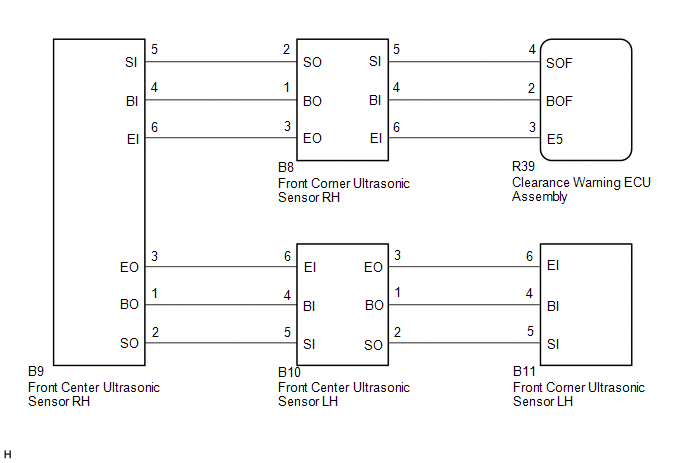
WIRING DIAGRAM
CAUTION / NOTICE / HINT
NOTICE:
- Perform registration after replacing or removing and installing the ultrasonic sensor or clearance warning ECU assembly.
Click here
.gif)
- If a DTC is detected again after the repair, turn the ignition switch to ON and turn the intuitive parking assist system on, and then clear the DTC.
Click here
- If C1AE496 is output at the same time, check C1AE496 first.
Click here
PROCEDURE
|
1. | VEHICLE CONDITION AND WORK DETAILS CHECK |
(a) Check the vehicle condition and work details.
|
Result | Proceed to |
|---|---|
|
The clearance warning ECU assembly or ultrasonic sensor has not been replaced |
A |
| The clearance warning ECU assembly or ultrasonic sensor has been replaced |
B |
| B |
.gif) | GO TO CALIBRATION |
|
.gif)
| 2. |
CHECK CONNECTOR CONNECTION CONDITION (ULTRASONIC SENSOR) |
(a) Check that the connector is properly connected to the front corner ultrasonic sensor and front center ultrasonic sensor.
|
| 3. |
CHECK FOR DTC |
(a) According to the display on the GTS, check for DTCs.
Body Electrical > Clearance Warning > Trouble Codes(b) According to the display on the GTS, clear the DTCs.
Body Electrical > Clearance Warning > Clear DTCs(c) Recheck for DTCs.
Body Electrical > Clearance Warning > Trouble Codes|
Result | Proceed to |
|---|---|
|
C1AE387 is not output |
A |
| C1AE387 is output |
B |
| A |
| END (CONNECTOR CONNECTION MALFUNCTION) |
|
| 4. |
CHECK CONNECTOR CONNECTION CONDITION (CLEARANCE WARNING ECU ASSEMBLY) |
(a) Check that the connector is properly connected to the clearance warning ECU assembly.
|
| 5. |
CHECK FOR DTC |
(a) According to the display on the GTS, check for DTCs.
Body Electrical > Clearance Warning > Trouble Codes(b) According to the display on the GTS, clear the DTCs.
Body Electrical > Clearance Warning > Clear DTCs(c) Recheck for DTCs.
Body Electrical > Clearance Warning > Trouble Codes DTC OUTPUT COMBINATION:|
Symptoms | DTC Detection | |||
|---|---|---|---|---|
|
C1AE487 | C1AE387 |
C1AE287 | C1AE187 | |
|
Symptom 1 | Not output |
Not output | Not output |
Not output |
|
Symptom 2 | Output |
Output | Output |
Output |
| Symptom 3 |
Not output | Output |
Output | Output |
|
Symptom 4 | Not output |
Not output | Output |
Output |
| Symptom 5 |
Not output | Not output |
Not output | Output |
|
Symptom 6 | Not output |
Output | Not output |
Not output |
|
Result | Proceed to |
|---|---|
|
Listed under symptom 1 in combination table |
A |
| Listed under symptom 2 in combination table |
B |
| Listed under symptom 3 in combination table |
C |
| Listed under symptom 4 in combination table |
D |
| Listed under symptom 5 in combination table |
E |
| Listed under symptom 6 in combination table |
F |
| A |
| USE SIMULATION METHOD TO CHECK
|
| B |
| GO TO CORRESPONDING FLOWCHART (INTUITIVE PARKING ASSIST SYSTEM (C1AE487)) |
| D |
| GO TO CORRESPONDING FLOWCHART (INTUITIVE PARKING ASSIST SYSTEM (C1AE287)) |
| E |
| GO TO CORRESPONDING FLOWCHART (INTUITIVE PARKING ASSIST SYSTEM (C1AE187)) |
| F |
| GO TO STEP 7 |
|
| 6. |
CHECK WIRE HARNESS AND CONNECTOR (FRONT CORNER ULTRASONIC SENSOR RH - FRONT CENTER ULTRASONIC SENSOR RH) |
(a) Disconnect the B8 front corner ultrasonic sensor RH connector.
(b) Disconnect the B9 front center ultrasonic sensor RH connector.
(c) Measure the resistance according to the value(s) in the table below.
Standard Resistance:
|
Tester Connection | Condition |
Specified Condition |
|---|---|---|
|
B8-1 (BO) - B9-4 (BI) |
Always | Below 1 Ω |
|
B8-2 (SO) - B9-5 (SI) |
Always | Below 1 Ω |
|
B8-3 (EO) - B9-6 (EI) |
Always | Below 1 Ω |
|
B8-1 (BO) or B9-4 (BI) - Body ground |
Always | 10 kΩ or higher |
|
B8-2 (SO) or B9-5 (SI) - Body ground |
Always | 10 kΩ or higher |
|
B8-3 (EO) or B9-6 (EI) - Body ground |
Always | 10 kΩ or higher |
| NG | | REPAIR OR REPLACE WIRE HARNESS OR CONNECTOR |
|
| 7. |
REPLACE FRONT CENTER ULTRASONIC SENSOR RH |
(a) Replace the front center ultrasonic sensor RH with a new or normally functioning one.
Click here
HINT:
To check if the ultrasonic sensor is functioning correctly, replace it with another ultrasonic sensor.
|
| 8. |
RECHECK FOR DTC |
(a) According to the display on the GTS, check for DTCs.
Body Electrical > Clearance Warning > Trouble Codes(b) According to the display on the GTS, clear the DTCs.
Body Electrical > Clearance Warning > Clear DTCs(c) Recheck for DTCs.
Body Electrical > Clearance Warning > Trouble Codes|
Result | Proceed to |
|---|---|
|
No DTC is output | A |
|
"C1AE387" is output | B |
| A |
| END (FRONT CENTER ULTRASONIC SENSOR RH WAS DEFECTIVE) |
| B |
| REPLACE CLEARANCE WARNING ECU ASSEMBLY |
READ NEXT:
 Ultrasonic Sensor (Front Right Center) Component Internal Failure (C1AE396)
DESCRIPTION The front center ultrasonic sensor RH is installed on the front bumper. The clearance warning ECU assembly detects obstacles based on signals it receives from the front center ultrasonic s
Ultrasonic Sensor (Front Right Corner) Missing Message (C1AE487)
DESCRIPTION This DTC is stored when an open circuit or short occurs in the communication line between the front corner ultrasonic sensor RH and the clearance warning ECU, or when a malfunction occurs
SEE MORE:
Terminals Of Ecu
TERMINALS OF ECU CHECK 4WD ECU ASSEMBLY
(a) Measure the voltage and resistance of the connector.
Terminal No. (Symbol) Wiring Color
Terminal Description Condition
Specified Condition
K145-6 (CANH) - K145-5 (CANL)
P - W HIGH-level CAN bus wire - LOW-level CAN bu
Wireless charger (if equipped)
A portable device, such as a smartphone or mobile battery, can be
charged by just placing it on the charging area, provided the device is
compatible with the Qi wireless charging standard created by the
Wireless Power Consortium.
The wireless charger cannot be used with a portable device that
