Toyota Camry (XV70): Voice Recognition Microphone Disconnected (B1579)
DESCRIPTION
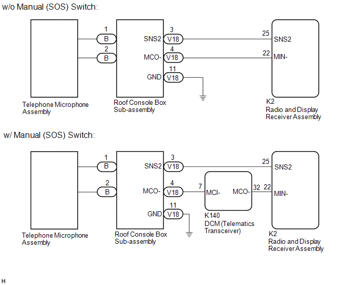
The radio and display receiver assembly, roof console box sub-assembly and telephone microphone assembly are connected to each other using the microphone connection detection signal lines.
This DTC is stored when a microphone connection detection signal line is disconnected.
|
DTC No. | Detection Item |
DTC Detection Condition | Trouble Area |
|---|---|---|---|
|
B1579 | Voice Recognition Microphone Disconnected |
Microphone signal is lost |
|
- *: w/ Manual (SOS) Switch
WIRING DIAGRAM
w/ Sliding Roof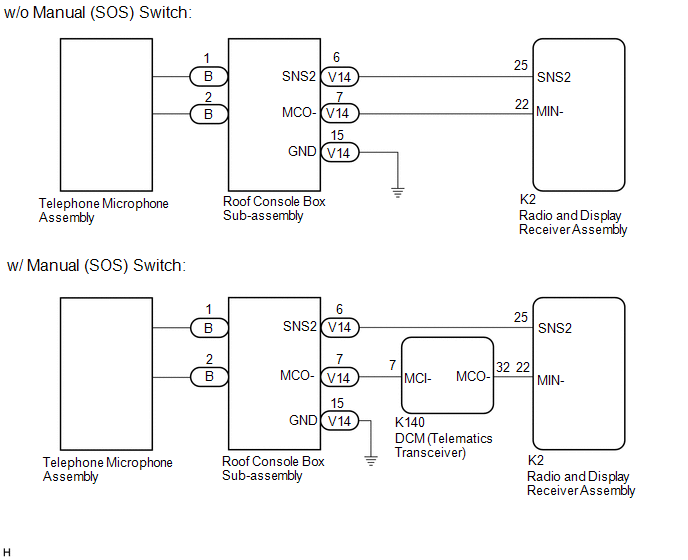 w/o Sliding Roof
CAUTION / NOTICE / HINT
NOTICE:
- Depending on the parts that are replaced during vehicle inspection or maintenance, performing initialization, registration or calibration may be needed. Refer to Precaution for Audio and Visual System.
Click here
.gif)
- When replacing the radio and display receiver assembly, always replace it with a new one. If a radio and display receiver assembly which was installed to another vehicle is used, the following may occur:
- A communication malfunction DTC may be stored.
- The radio and display receiver assembly may not operate normally.
- Before replacing the DCM (telematics transceiver), refer to Registration.
Click here
PROCEDURE
|
1. | CHECK MODEL |
(a) Choose the model to be inspected.
|
Result | Proceed to |
|---|---|
|
w/ Sliding Roof | A |
|
w/o Sliding Roof | B |
| B |
.gif) | GO TO STEP 10 |
|
.gif)
| 2. |
INSPECT RADIO AND DISPLAY RECEIVER ASSEMBLY |
| (a) Measure the resistance according to the value(s) in the table below. Standard Resistance:
Result:
|
|
| B |
| GO TO STEP 4 |
| C |
| REPLACE RADIO AND DISPLAY RECEIVER ASSEMBLY
|
|
| 3. |
CHECK HARNESS AND CONNECTOR (RADIO AND DISPLAY RECEIVER ASSEMBLY - ROOF CONSOLE BOX SUB-ASSEMBLY) |
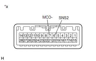
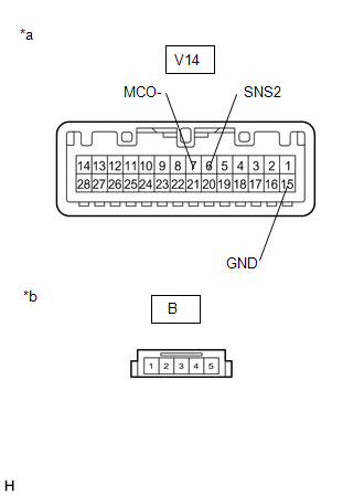
(a) Disconnect the K2 radio and display receiver assembly connector.
(b) Disconnect the V14 roof console box sub-assembly connector.
(c) Measure the resistance according to the value(s) in the table below.
Standard Resistance:
|
Tester Connection | Condition |
Specified Condition |
|---|---|---|
|
K2-25 (SNS2) - V14-6 (SNS2) |
Always | Below 1 Ω |
|
K2-22 (MIN-) - V14-7 (MCO-) |
Always | Below 1 Ω |
|
K2-25 (SNS2) or V14-6 (SNS2) - Body ground |
Always | 10 kΩ or higher |
|
K2-22 (MIN-) or V14-7 (MCO-) - Body ground |
Always | 10 kΩ or higher |
| OK | | GO TO STEP 8 |
| NG | | REPAIR OR REPLACE HARNESS OR CONNECTOR |
| 4. |
CHECK HARNESS AND CONNECTOR (DCM (TELEMATICS TRANSCEIVER) - ROOF CONSOLE BOX SUB-ASSEMBLY) |
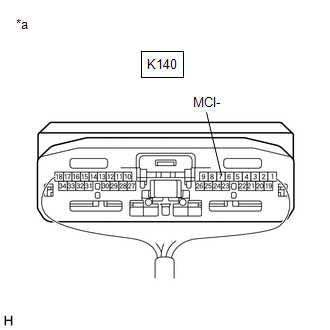
(a) Disconnect the K140 DCM (telematics transceiver) connector.
(b) Disconnect the V14 roof console box sub-assembly connector.
(c) Measure the resistance according to the value(s) in the table below.
Standard Resistance:
|
Tester Connection | Condition |
Specified Condition |
|---|---|---|
|
K140-7 (MCI-) - V14-7 (MCO-) |
Always | Below 1 Ω |
|
K140-7 (MCI-) or V14-7 (MCO-) - Body ground |
Always | 10 kΩ or higher |
| NG | | REPAIR OR REPLACE HARNESS OR CONNECTOR |
|
| 5. |
CHECK HARNESS AND CONNECTOR (RADIO AND DISPLAY RECEIVER ASSEMBLY - DCM (TELEMATICS TRANSCEIVER)) |
(a) Disconnect the K2 radio and display receiver assembly connector.
(b) Disconnect the K140 DCM (telematics transceiver) connector.
(c) Measure the resistance according to the value(s) in the table below.
Standard Resistance:
|
Tester Connection | Condition |
Specified Condition |
|---|---|---|
|
K2-22 (MIN-) - K140-32 (MCO-) |
Always | Below 1 Ω |
|
K2-22 (MIN-) or K140-32 (MCO-) - Body ground |
Always | 10 kΩ or higher |
| NG | | REPAIR OR REPLACE HARNESS OR CONNECTOR |
|
| 6. |
CHECK HARNESS AND CONNECTOR (RADIO AND DISPLAY RECEIVER ASSEMBLY - ROOF CONSOLE BOX SUB-ASSEMBLY) |
(a) Disconnect the K2 radio and display receiver assembly connector.
(b) Disconnect the V14 roof console box sub-assembly connector.
(c) Measure the resistance according to the value(s) in the table below.
Standard Resistance:
|
Tester Connection | Condition |
Specified Condition |
|---|---|---|
|
K2-25 (SNS2) - V14-6 (SNS2) |
Always | Below 1 Ω |
|
K2-25 (SNS2) or V14-6 (SNS2) - Body ground |
Always | 10 kΩ or higher |
| NG | | REPAIR OR REPLACE HARNESS OR CONNECTOR |
|
| 7. |
INSPECT DCM (TELEMATICS TRANSCEIVER) |
(a) Connect the K140 DCM (telematics transceiver) connector.
(b) Connect the K2 radio and display receiver assembly connector.
| (c) Measure the resistance according to the value(s) in the table below. Standard Resistance:
|
|
| NG | | REPLACE DCM (TELEMATICS TRANSCEIVER)
|
|
| 8. |
INSPECT ROOF CONSOLE BOX SUB-ASSEMBLY |
(a) Remove the roof console box sub-assembly.
Click here
(b) Connect the B telephone microphone assembly connector.
| (c) Measure the resistance according to the value(s) in the table below. Standard Resistance:
|
|
| OK | | REPLACE RADIO AND DISPLAY RECEIVER ASSEMBLY
|
|
| 9. |
INSPECT ROOF CONSOLE BOX SUB-ASSEMBLY |
(a) Remove the roof console box sub-assembly.
Click here
(b) Disconnect the B telephone microphone assembly connector.
| (c) Measure the resistance according to the value(s) in the table below. Standard Resistance:
|
|
| OK | | REPLACE TELEPHONE MICROPHONE ASSEMBLY |
| NG | | REPLACE ROOF CONSOLE BOX SUB-ASSEMBLY |
| 10. |
INSPECT RADIO AND DISPLAY RECEIVER ASSEMBLY |
| (a) Measure the resistance according to the value(s) in the table below. Standard Resistance:
Result:
|
|
| B |
| GO TO STEP 12 |
| C |
| REPLACE RADIO AND DISPLAY RECEIVER ASSEMBLY
|
|
| 11. |
CHECK HARNESS AND CONNECTOR (RADIO AND DISPLAY RECEIVER ASSEMBLY - ROOF CONSOLE BOX SUB-ASSEMBLY) |
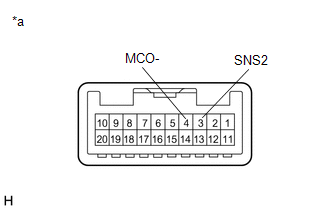
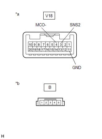
(a) Disconnect the K2 radio and display receiver assembly connector.
(b) Disconnect the V18 roof console box sub-assembly connector.
(c) Measure the resistance according to the value(s) in the table below.
Standard Resistance:
|
Tester Connection | Condition |
Specified Condition |
|---|---|---|
|
K2-25 (SNS2) - V18-3 (SNS2) |
Always | Below 1 Ω |
|
K2-22 (MIN-) - V18-4 (MCO-) |
Always | Below 1 Ω |
|
K2-25 (SNS2) or V18-3 (SNS2) - Body ground |
Always | 10 kΩ or higher |
|
K2-22 (MIN-) or V18-4 (MCO-) - Body ground |
Always | 10 kΩ or higher |
| OK | | GO TO STEP 16 |
| NG | | REPAIR OR REPLACE HARNESS OR CONNECTOR |
| 12. |
CHECK HARNESS AND CONNECTOR (DCM (TELEMATICS TRANSCEIVER) - ROOF CONSOLE BOX SUB-ASSEMBLY) |
(a) Disconnect the K140 DCM (telematics transceiver) connector.
(b) Disconnect the V18 roof console box sub-assembly connector.
(c) Measure the resistance according to the value(s) in the table below.
Standard Resistance:
|
Tester Connection | Condition |
Specified Condition |
|---|---|---|
|
K140-7 (MCI-) - V18-4 (MCO-) |
Always | Below 1 Ω |
|
K140-7 (MCI-) or V18-4 (MCO-) - Body ground |
Always | 10 kΩ or higher |
| NG | | REPAIR OR REPLACE HARNESS OR CONNECTOR |
|
| 13. |
CHECK HARNESS AND CONNECTOR (RADIO AND DISPLAY RECEIVER ASSEMBLY - DCM (TELEMATICS TRANSCEIVER)) |
(a) Disconnect the K2 radio and display receiver assembly connector.
(b) Disconnect the K140 DCM (telematics transceiver) connector.
(c) Measure the resistance according to the value(s) in the table below.
Standard Resistance:
|
Tester Connection | Condition |
Specified Condition |
|---|---|---|
|
K2-22 (MIN-) - K140-32 (MCO-) |
Always | Below 1 Ω |
|
K2-22 (MIN-) or K140-32 (MCO-) - Body ground |
Always | 10 kΩ or higher |
| NG | | REPAIR OR REPLACE HARNESS OR CONNECTOR |
|
| 14. |
CHECK HARNESS AND CONNECTOR (RADIO AND DISPLAY RECEIVER ASSEMBLY - ROOF CONSOLE BOX SUB-ASSEMBLY) |
(a) Disconnect the K2 radio and display receiver assembly connector.
(b) Disconnect the V18 roof console box sub-assembly connector.
(c) Measure the resistance according to the value(s) in the table below.
Standard Resistance:
|
Tester Connection | Condition |
Specified Condition |
|---|---|---|
|
K2-25 (SNS2) - V18-3 (SNS2) |
Always | Below 1 Ω |
|
K2-25 (SNS2) or V18-3 (SNS2) - Body ground |
Always | 10 kΩ or higher |
| NG | | REPAIR OR REPLACE HARNESS OR CONNECTOR |
|
| 15. |
INSPECT DCM (TELEMATICS TRANSCEIVER) |
(a) Connect the K140 DCM (telematics transceiver) connector.
(b) Connect the K2 radio and display receiver assembly connector.
| (c) Measure the resistance according to the value(s) in the table below. Standard Resistance:
|
|
| NG | | REPLACE DCM (TELEMATICS TRANSCEIVER)
|
|
| 16. |
INSPECT ROOF CONSOLE BOX SUB-ASSEMBLY |
(a) Remove the roof console box sub-assembly.
Click here
(b) Connect the B telephone microphone assembly connector.
| (c) Measure the resistance according to the value(s) in the table below. Standard Resistance:
|
|
| OK | | REPLACE RADIO AND DISPLAY RECEIVER ASSEMBLY
|
|
| 17. |
INSPECT ROOF CONSOLE BOX SUB-ASSEMBLY |
(a) Remove the roof console box sub-assembly.
Click here
(b) Disconnect the B telephone microphone assembly connector.
| (c) Measure the resistance according to the value(s) in the table below. Standard Resistance:
|
|
| OK | | REPLACE TELEPHONE MICROPHONE ASSEMBLY |
| NG | | REPLACE ROOF CONSOLE BOX SUB-ASSEMBLY |
READ NEXT:
 USB Device Malfunction (B1585)
DESCRIPTION This DTC is stored when a malfunction occurs in a connected device.
DTC No. Detection Item
DTC Detection Condition Trouble Area
B1585 USB Device Malfunction
AV Signal Stoppage (Low Battery Voltage) (B158F)
DESCRIPTION This DTC is stored when a video or audio signal is interrupted due to battery voltage input to the radio and display receiver assembly dropping temporarily.
DTC No. Detection Item
Stereo Component Amplifier Malfunction (B15A3)
DESCRIPTION This DTC is stored when a malfunction occurs in the stereo component amplifier assembly.
DTC No. Detection Item
DTC Detection Condition Trouble Area
B15A3 Stereo C
SEE MORE:
Components
COMPONENTS ILLUSTRATION
*1 CLEARANCE WARNING ECU ASSEMBLY
*2 ECU INTEGRATION BOX RH
*3 LOWER INSTRUMENT PANEL SUB-ASSEMBLY
- -
N*m (kgf*cm, ft.*lbf): Specified torque
- -
Internal Control Module A/D Processing Performance Internal Electronic Failure (P060B49)
MONITOR DESCRIPTION This DTC is stored when a communication error occurs in the ECM.
DTC No. Detection Item
DTC Detection Condition Trouble Area
MIL Memory
Note P060B49
Internal Control Module A/D Processing Performance Internal Electronic Failure
ECM main
