Toyota Camry (XV70): AV Signal Stoppage (Low Battery Voltage) (B158F)
DESCRIPTION
This DTC is stored when a video or audio signal is interrupted due to battery voltage input to the radio and display receiver assembly dropping temporarily.
|
DTC No. | Detection Item |
DTC Detection Condition | Trouble Area |
|---|---|---|---|
|
B158F | AV Signal Stoppage (Low Battery Voltage) |
A video or audio signal is interrupted when the battery voltage drops |
|
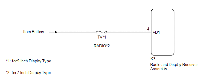
WIRING DIAGRAM
CAUTION / NOTICE / HINT
NOTICE:
- Depending on the parts that are replaced during vehicle inspection or maintenance, performing initialization, registration or calibration may be needed. Refer to Precaution for Audio and Visual System.
Click here
.gif)
- When replacing the radio and display receiver assembly, always replace it with a new one. If a radio and display receiver assembly which was installed to another vehicle is used, the following may occur:
- A communication malfunction DTC may be stored.
- The radio and display receiver assembly may not operate normally.
- Inspect the fuses for circuits related to this system before performing the following procedure.
PROCEDURE
|
1. | CHECK VEHICLE SIGNAL (OPERATION CHECK) |
| (a) Enter the "Vehicle Signal Check Mode" screen. Refer to Check Vehicle Signal in Operation Check. Click here |
|
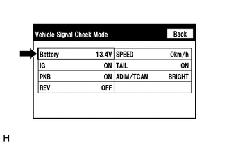
(b) Measure the battery voltage.
Standard Voltage:
11 to 14 V
HINT:
This display is updated once per second.
| NG | .gif) | GO TO STEP 3 |
|
.gif)
| 2. |
CHECK DTC |
(a) Clear the DTCs.
Body Electrical > Navigation System > Clear DTCs(b) Recheck for DTCs and check that no DTCs are output.
Body Electrical > Navigation System > Trouble CodesOK:
No DTCs are output.
| OK | |
END |
| NG | | REPLACE RADIO AND DISPLAY RECEIVER ASSEMBLY |
| 3. |
CHECK HARNESS AND CONNECTOR (RADIO AND DISPLAY RECEIVER ASSEMBLY POWER SOURCE) |
(a) Disconnect the K3 radio and display receiver assembly connector.
(b) Measure the voltage according to the value(s) in the table below.
Standard Voltage:
|
Tester Connection | Condition |
Specified Condition |
|---|---|---|
|
K3-4 (+B1) - Body ground |
Always | 11 to 14 V |
| OK | | REPLACE RADIO AND DISPLAY RECEIVER ASSEMBLY |
| NG | | REPAIR OR REPLACE HARNESS OR CONNECTOR |
READ NEXT:
 Stereo Component Amplifier Malfunction (B15A3)
DESCRIPTION This DTC is stored when a malfunction occurs in the stereo component amplifier assembly.
DTC No. Detection Item
DTC Detection Condition Trouble Area
B15A3 Stereo C
GPS Antenna Connection Malfunction(short) (B15C0,B15C1)
DESCRIPTION These DTCs are stored when a malfunction occurs in the navigation antenna assembly.
DTC No. Detection Item
DTC Detection Condition Trouble Area
B15C0 GPS Antenna C
Speaker Output Short (B15C3)
DESCRIPTION This DTC is stored when a malfunction occurs in the speakers.
DTC No. Detection Item
DTC Detection Condition Trouble Area
B15C3 Speaker Output Short
A short
SEE MORE:
Components
COMPONENTS ILLUSTRATION
*1 BATTERY CLAMP SUB-ASSEMBLY
- -
N*m (kgf*cm, ft.*lbf): Specified torque
- - ILLUSTRATION
*1 TRANSMISSION CONTROL CABLE ASSEMBLY
*2 TRANSMISSION CONTROL SHAFT LEVER
*3 PARK/NEUTRAL POSITION SWITCH AS
Torque Converter And Drive Plate
InspectionINSPECTION PROCEDURE
1. INSPECT TORQUE CONVERTER ASSEMBLY (a) Inspect the one-way clutch. Press on the splines of the stator with a finger and rotate it. Check that it rotates smoothly when turned clockwise and rotates with difficulty when turned counterclockwise.
Diffic
