Toyota Camry (XV70): Antenna Cord
Components
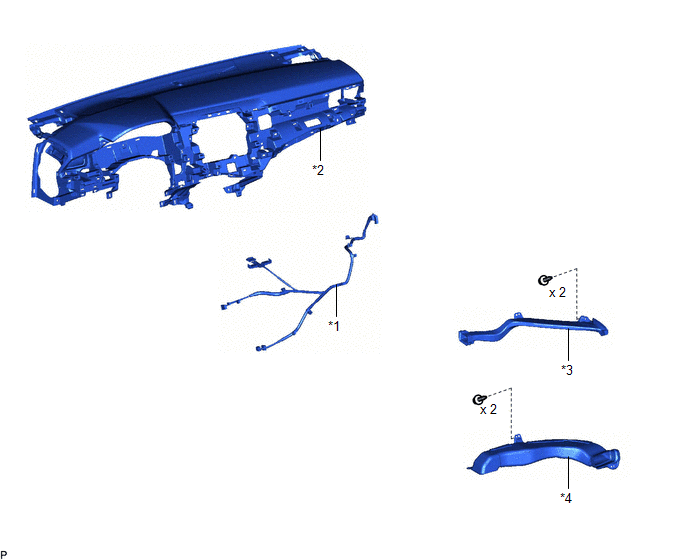
COMPONENTS
ILLUSTRATION
|
*1 | ANTENNA CORD SUB-ASSEMBLY |
*2 | INSTRUMENT PANEL SAFETY PAD SUB-ASSEMBLY |
|
*3 | NO. 2 SIDE DEFROSTER NOZZLE DUCT |
*4 | NO. 3 HEATER TO REGISTER DUCT SUB-ASSEMBLY |
Removal
REMOVAL
CAUTION / NOTICE / HINT
The necessary procedures (adjustment, calibration, initialization, or registration) that must be performed after parts are removed and installed, or replaced during antenna cord sub-assembly removal/installation are shown below.
Necessary Procedure After Parts Removed/Installed/Replaced|
Replaced Part or Performed Procedure |
Necessary Procedures | Effect/Inoperative Function when Necessary Procedure not Performed |
Link |
|---|---|---|---|
| Disconnect cable from negative battery terminal |
Perform steering sensor zero point calibration |
Lane Tracing Assist System |
|
|
Pre-collision System | |||
|
Memorize steering angle neutral point |
Parking Assist Monitor System |
| |
|
Panoramic View Monitor System |
|
CAUTION:
Some of these service operations affect the SRS airbag system. Read the precautionary notices concerning the SRS airbag system before servicing.
Click here .gif)
.png)
PROCEDURE
1. REMOVE INSTRUMENT PANEL SAFETY PAD SUB-ASSEMBLY
Click here
2. REMOVE NO. 2 SIDE DEFROSTER NOZZLE DUCT
Click here
3. REMOVE NO. 3 HEATER TO REGISTER DUCT SUB-ASSEMBLY
Click here
4. REMOVE ANTENNA CORD SUB-ASSEMBLY
(a) Disconnect the connector.
.png)
(b) Disengage the 2 claws.
(c) Disengage the 7 clamps to remove the antenna cord sub-assembly.
Installation
INSTALLATION
PROCEDURE
1. INSTALL ANTENNA CORD SUB-ASSEMBLY
(a) Engage the 7 clamps to install the antenna cord sub-assembly.
(b) Engage the 2 claws.
(c) Connect the connector.
2. INSTALL NO. 3 HEATER TO REGISTER DUCT SUB-ASSEMBLY
Click here .gif)
3. INSTALL NO. 2 SIDE DEFROSTER NOZZLE DUCT
Click here
4. INSTALL INSTRUMENT PANEL SAFETY PAD SUB-ASSEMBLY
Click here
READ NEXT:
 Components
COMPONENTS ILLUSTRATION
*A w/o Manual (SOS) Switch
*B w/ Manual (SOS) Switch
*1 INSTRUMENT PANEL SAFETY PAD SUB-ASSEMBLY
*2 NAVIGATION ANTENNA ASSEMBLY
*3
Removal
REMOVAL CAUTION / NOTICE / HINT
The necessary procedures (adjustment, calibration, initialization, or registration) that must be performed after parts are removed and installed, or replaced during n
SEE MORE:
Slip Indicator Light Remains ON
DESCRIPTION This procedure is for troubleshooting when the slip indicator light remains on but no DTCs are output.
The skid control ECU (brake actuator assembly) controls the slip indicator light in the combination meter assembly via CAN communication.
The slip indicator light blinks during VSC
Left Front Wheel Speed Sensor Internal Electronic Failure (C050049)
DESCRIPTION When the system is starting up and the skid control ECU (brake actuator assembly) detects a speed sensor circuit malfunction via the speed sensor circuit self-diagnosis function, this DTC is stored.
DTC No. Detection Item
DTC Detection Condition Trouble Area
C05004
