Toyota Camry (XV70): Components
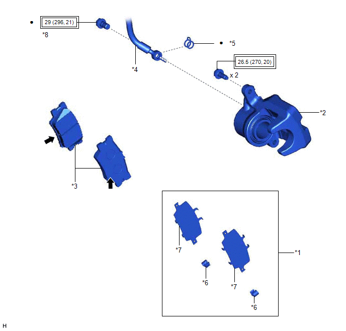
COMPONENTS
ILLUSTRATION
|
*1 | REAR DISC BRAKE ANTI-SQUEAL SHIM KIT |
*2 | REAR DISC BRAKE CYLINDER ASSEMBLY |
|
*3 | REAR DISC BRAKE PAD |
*4 | REAR FLEXIBLE HOSE |
|
*5 | GASKET |
*6 | REAR DISC BRAKE PAD WEAR INDICATOR PLATE |
|
*7 | REAR NO. 1 DISC BRAKE ANTI-SQUEAL SHIM |
*8 | UNION BOLT |
.png) |
Tightening torque for "Major areas involving basic vehicle performance such as moving/turning/stopping" : N*m (kgf*cm, ft.*lbf) |
● | Non-reusable part |
.png) |
Brake shim grease (Part No. 08887-80409) |
- | - |
ILLUSTRATION
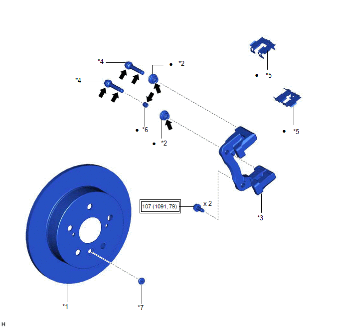
|
*1 | REAR DISC |
*2 | REAR DISC BRAKE BUSHING DUST BOOT |
|
*3 | REAR DISC BRAKE CYLINDER MOUNTING |
*4 | REAR DISC BRAKE CYLINDER SLIDE PIN |
|
*5 | REAR DISC BRAKE PAD SUPPORT PLATE |
*6 | REAR DISC BRAKE CYLINDER SLIDE BUSHING |
|
*7 | PARKING BRAKE SHOE ADJUSTING HOLE PLUG |
- | - |
|
|
Tightening torque for "Major areas involving basic vehicle performance such as moving/turning/stopping" : N*m (kgf*cm, ft.*lbf) |
● | Non-reusable part |
|
|
Lithium soap base glycol grease |
- | - |
ILLUSTRATION
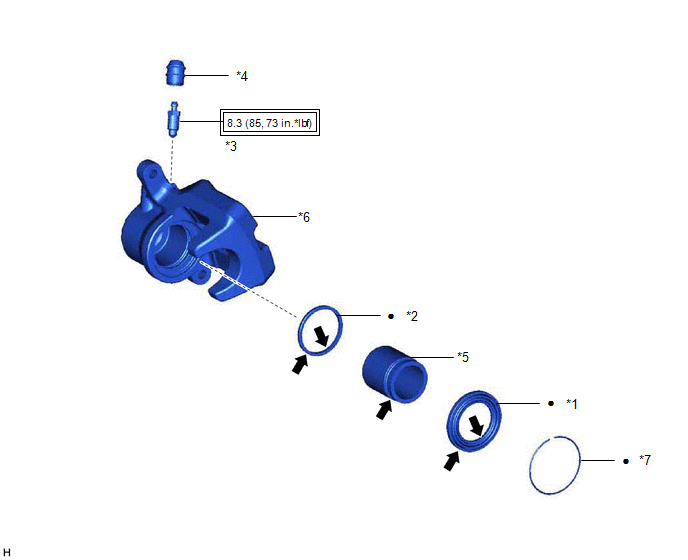
|
*1 | CYLINDER BOOT |
*2 | PISTON SEAL |
|
*3 | REAR DISC BRAKE BLEEDER PLUG |
*4 | REAR DISC BRAKE BLEEDER PLUG CAP |
|
*5 | REAR DISC BRAKE PISTON |
*6 | REAR DISC BRAKE CYLINDER |
|
*7 | REAR DISC BRAKE PISTON SET RING |
- | - |
|
|
Tightening torque for "Major areas involving basic vehicle performance such as moving/turning/stopping" : N*m (kgf*cm, ft.*lbf) |
● | Non-reusable part |
|
|
Lithium soap base glycol grease |
- | - |
READ NEXT:
 Removal
REMOVAL CAUTION / NOTICE / HINT
NOTICE:
Immediately after installing the brake pads, the braking performance may be reduced. Always perform a road test in a safe place while paying attention to
Disassembly
DISASSEMBLY PROCEDURE 1. REMOVE CYLINDER BOOT
(a) Using a screwdriver with its tip wrapped with protective tape, remove the rear disc brake piston set ring and cylinder boot from the rear disc b
Inspection
INSPECTION PROCEDURE 1. INSPECT BRAKE CYLINDER AND PISTON
(a) Check the rear disc brake cylinder bore and rear disc brake piston for rust and scoring. If necessary, replace the rear disc brake cylin
SEE MORE:
Components
COMPONENTS ILLUSTRATION
*A for Type A
*B for Type B
*1 COMPRESSOR ASSEMBLY WITH MAGNETIC CLUTCH
*2 DRIVE SHAFT BEARING BRACKET
*3 ENGINE COVER BRACKET
*4 ENGINE OIL LEVEL DIPSTICK GUIDE
*5 GENERATOR ASSEMBLY
*6 IGNITION COIL A
Removal
REMOVAL CAUTION / NOTICE / HINT
The necessary procedures (adjustment, calibration, initialization or registration) that must be performed after parts are removed and installed, or replaced during ECM removal/installation are shown below. Necessary Procedures After Parts Removed/Installed/Replaced
