Toyota Camry (XV70): Disassembly
DISASSEMBLY
CAUTION / NOTICE / HINT
NOTICE:
- As imbalance affects vibration and noise performance, make sure to ensure correct angular alignment of the following components during installation.
- PROPELLER INTERMEDIATE SHAFT ASSEMBLY
- REAR PROPELLER SHAFT ASSEMBLY
- LARGE DIAMETER PROPELLER SHAFT BOOT CLAMP
- SMALL DIAMETER PROPELLER SHAFT BOOT CLAMP
- BALL CAGE, INNER RACE
- When using a vise, place aluminum plates between the part and vise.
- When using a vise, do not overtighten it.
PROCEDURE
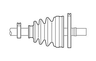
1. REMOVE REAR PROPELLER SHAFT ASSEMBLY
NOTICE:
As the rear propeller shaft assembly requires alignment of multiple matchmarks, it is necessary to make separately distinguishable matchmarks.
| (a) Put matchmarks on the propeller intermediate shaft assembly and rear propeller shaft assembly. NOTICE: Do not use a punch for the marks. |
|
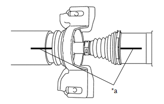
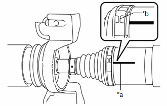
| (b) Put a matchmark on the rear propeller shaft assembly in alignment with the crimp position of the small diameter propeller shaft boot clamp. |
|
| (c) Put a matchmark on the rear propeller shaft assembly in alignment with the crimp position of the large diameter propeller shaft boot clamp. |
|
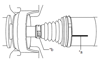
| (d) Using a screwdriver, release the crimp of the large diameter propeller shaft boot clamp and separate the large diameter propeller shaft boot clamp from the propeller shaft boot. |
|
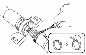
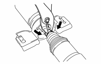
| (e) Using pliers, grip the crimp area of the clamp and pry the area of the small diameter propeller shaft boot clamp shown in the illustration to separate the small diameter propeller shaft boot clamp from the propeller shaft boot. |
|
(f) Separate the propeller shaft boot from the rear propeller shaft assembly.
(g) Remove the old grease from the joint part.
(h) Remove the rear propeller shaft assembly from the propeller intermediate shaft assembly.
2. REMOVE UNIVERSAL BOOT KIT
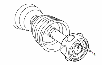
| (a) Put matchmarks on the propeller intermediate shaft assembly, inner race and ball cage. NOTICE: Do not use a punch for the marks. |
|
(b) Remove the 6 balls.
NOTICE:
Do not drop the balls.
| (c) Slide the ball cage toward the front side. |
|
(d) Using a snap ring expander, remove the propeller shaft snap ring from the propeller intermediate shaft assembly.
| (e) Using a brass bar and a hammer, tap out the inner race from the propeller intermediate shaft assembly. NOTICE: Do not drop the inner race. |
|
(f) Remove the ball cage.
| (g) Remove the large diameter propeller shaft boot clamp, propeller shaft boot and small diameter propeller shaft boot clamp. |
|
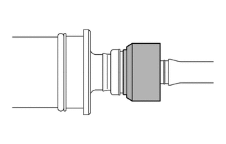
3. REMOVE CENTER SUPPORT BEARING
| (a) Cut off the rubber portion of the center support bearing and remove the bracket. |
|
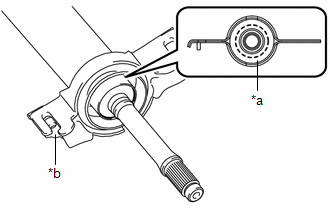
| (b) Remove any excess rubber so the center support bearing appears as shown in the illustration. |
|
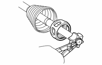
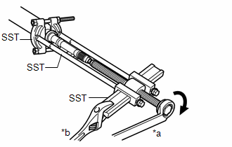
| (c) Install SST as shown in the illustration. SST: 09950-00020 SST: 09950-00040 SST: 09950-40011 09951-04020 09952-04010 09953-04020 09954-04020 09957-04010 NOTICE: Securely install SST between the center support bearing and No. 1 dust deflector. |
|
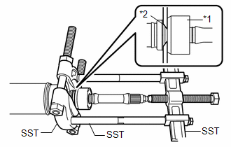
(d) Apply grease to the threaded area of the SST center bolt.
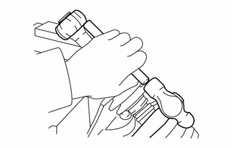
| (e) Using SST, remove the center support bearing and flange from the propeller intermediate shaft assembly. SST: 09950-00020 SST: 09950-00040 SST: 09950-40011 09951-04020 09952-04010 09953-04020 09954-04020 09957-04010 HINT: Perform this procedure with 2 or more people and prevent the propeller shaft from rotating. |
|
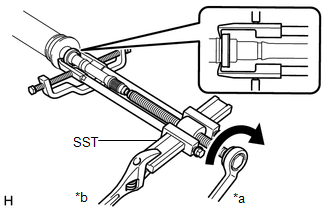
| (f) Using SST, remove the No. 1 dust deflector. SST: 09950-40011 09951-04020 09952-04010 09953-04020 09954-04030 09955-04031 09957-04010 09958-04011 |
|
READ NEXT:
 Inspection
INSPECTION PROCEDURE 1. INSPECT PROPELLER WITH CENTER BEARING SHAFT ASSEMBLY
(a) Using a dial indicator, measure the runout of the rear propeller shaft assembly (for front side).
Maximum Runo
Reassembly
REASSEMBLY CAUTION / NOTICE / HINT
NOTICE:
As imbalance affects vibration and noise performance, make sure to ensure correct angular alignment of the following components during installation.
Installation
INSTALLATION PROCEDURE 1. TEMPORARILY TIGHTEN PROPELLER WITH CENTER BEARING SHAFT ASSEMBLY
(a) When reusing a propeller with center bearing shaft assembly and rear differential carrier assembly:
SEE MORE:
Data List / Active Test
DATA LIST / ACTIVE TEST DATA LIST HINT:
Using the Techstream to read the Data List allows the values or states of switches, sensors, actuators and other items to be read without removing any parts. This non-intrusive inspection can be very useful because intermittent conditions or signals may be d
Installation
INSTALLATION PROCEDURE 1. INSTALL V-RIBBED BELT
HINT: When reusing the V-ribbed belt, check the ribs and back of the V-ribbed belt for wear and cracks. If wear or a crack that reaches the core (at more than 1 point) is found, replace the V-ribbed belt.
(a) Set the V-ribbed belt onto each pul
