Toyota Camry (XV70): Inspection
INSPECTION
PROCEDURE
1. INSPECT PROPELLER WITH CENTER BEARING SHAFT ASSEMBLY
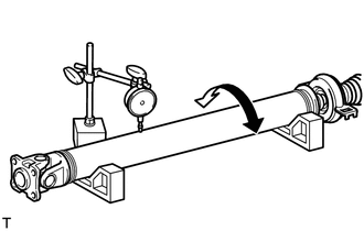
| (a) Using a dial indicator, measure the runout of the rear propeller shaft assembly (for front side). Maximum Runout: 0.6 mm (0.0236 in.) NOTICE: The dial indicator must be set at a right angle to the center of the rear propeller shaft assembly. If the shaft runout exceeds the maximum, replace the propeller with center bearing shaft assembly. |
|
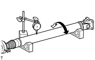
| (b) Using a dial indicator, measure the runout of the rear propeller shaft assembly (for rear side). Maximum Runout: 0.6 mm (0.0236 in.) NOTICE: The dial indicator must be set at a right angle to the center of the rear propeller shaft assembly. If the shaft runout exceeds the maximum, replace the propeller with center bearing shaft assembly. |
|
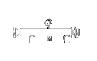
| (c) Using a dial indicator, measure the runout of the intermediate shaft assembly. Maximum Runout: 0.6 mm (0.0236 in.) NOTICE: The dial indicator must be set at a right angle to the center of the intermediate shaft assembly. If the shaft runout exceeds the maximum, replace the propeller with center bearing shaft assembly. |
|
(d) Check that there is no excessive play and the joint part moves smoothly when moving the joint part up and down, left and right, and in the direction of the axis.
READ NEXT:
 Reassembly
REASSEMBLY CAUTION / NOTICE / HINT
NOTICE:
As imbalance affects vibration and noise performance, make sure to ensure correct angular alignment of the following components during installation.
Installation
INSTALLATION PROCEDURE 1. TEMPORARILY TIGHTEN PROPELLER WITH CENTER BEARING SHAFT ASSEMBLY
(a) When reusing a propeller with center bearing shaft assembly and rear differential carrier assembly:
Propeller Shaft System
Problem Symptoms TablePROBLEM SYMPTOMS TABLE
HINT: Use the table below to help determine the cause of problem symptoms. If multiple suspected areas are listed, the potential causes of the symptoms a
SEE MORE:
Satellite Radio Broadcast cannot be Received
CAUTION / NOTICE / HINT NOTICE: Some satellite radio broadcasts require payment. A contract must be made between a satellite radio company and the user. If the contract expires, it will not be possible to listen to the broadcast. PROCEDURE
1.
CHECK SURROUNDINGS (a) Check if the vehicle
Reverse Signal Circuit between Radio Receiver Assembly and Navigation ECU
DESCRIPTION This circuit includes the navigation ECU and radio and display receiver assembly. WIRING DIAGRAM
PROCEDURE
1.
CHECK HARNESS AND CONNECTOR (RADIO AND DISPLAY RECEIVER ASSEMBLY - NAVIGATION ECU)
(a) Disconnect the K1 radio and display receiver assembly connector. (b) Dis
