Toyota Camry (XV70): Emergency Call Switch Circuit Short to Ground (B15C511,B15C513)
DESCRIPTION
If the DCM (telematics transceiver) detects an error in the communication between the DCM (telematics transceiver) and the roof console box sub-assembly (manual (SOS) switch) as a result of the DCM (telematics transceiver) self check, this DTC will be stored.
|
DTC No. | Detection Item |
DTC Detection Condition | Trouble Area |
|---|---|---|---|
|
B15C511 | Emergency Call Switch Circuit Short to Ground |
Manual (SOS) switch impedance (Ω) is lower than the malfunction threshold for 10 seconds or more when the engine switch is on (IG) |
|
| B15C513 |
Emergency Call Switch Circuit Open |
Manual (SOS) switch impedance (Ω) is higher than the malfunction threshold for 10 seconds or more when the engine switch is on (IG) |
|
WIRING DIAGRAM
w/ Sliding Roof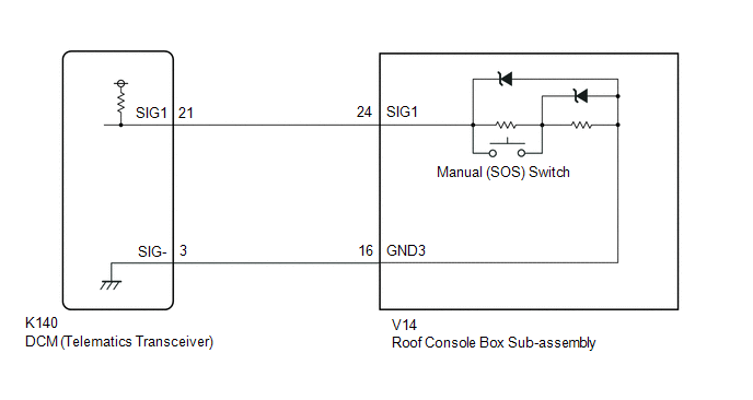 w/o Sliding Roof

CAUTION / NOTICE / HINT
NOTICE:
Depending on the parts that are replaced during vehicle inspection or maintenance, performing initialization, registration or calibration may be needed. Refer to Precaution for Safety Connect System.
Click here .gif)
PROCEDURE
| 1. |
CHECK DTC |
(a) Turn the engine switch off.
(b) Connect the Techstream to the DLC3.
(c) Turn the engine switch on (IG) and wait for 10 seconds or more.
(d) Turn the Techstream on.
(e) Clear the DTCs.
Body Electrical > Telematics > Clear DTCs(f) Check for DTCs and check that no DTCs are output.
Body Electrical > Telematics > Trouble CodesOK:
No DTCs are output.
| OK | .gif) |
USE SIMULATION METHOD TO CHECK |
|
.gif)
| 2. |
CONFIRM MODEL |
(a) Choose the model to be inspected.
| Result |
Proceed to |
|---|---|
| w/ Sliding Roof |
A |
| w/o Sliding Roof |
B |
| B |
| GO TO STEP 5 |
|
| 3. |
INSPECT ROOF CONSOLE BOX SUB-ASSEMBLY (MANUAL (SOS) SWITCH) |
| (a) Remove the roof console box sub-assembly (manual (SOS) switch). Click here |
|
(b) Measure the resistance according to the value(s) in the table below.
Standard Resistance:
|
Tester Connection | Condition |
Specified Condition |
|---|---|---|
|
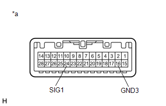
24 (SIG1) - 16 (GND3) |
Manual (SOS) switch not operated |
410 to 414 Ω |
|
24 (SIG1) - 16 (GND3) |
Manual (SOS) switch operated |
81 to 83 Ω |
| NG | | REPLACE ROOF CONSOLE BOX SUB-ASSEMBLY (MANUAL (SOS) SWITCH) |
|
| 4. |
CHECK HARNESS AND CONNECTOR (DCM (TELEMATICS TRANSCEIVER) - ROOF CONSOLE BOX SUB-ASSEMBLY (MANUAL (SOS) SWITCH)) |
(a) Disconnect the K140 DCM (telematics transceiver) connector.
(b) Disconnect the V14 roof console box sub-assembly (manual (SOS) switch) connector.
(c) Measure the resistance according to the value(s) in the table below.
Standard Resistance:
|
Tester Connection | Condition |
Specified Condition |
|---|---|---|
|
K140-21 (SIG1) - V14-24 (SIG1) |
Always | Below 1 Ω |
|
K140-3 (SIG-) - V14-16 (GND3) |
Always | Below 1 Ω |
|
K140-21 (SIG1) or V14-24 (SIG1) - Body ground |
Always | 10 kΩ or higher |
|
K140-3 (SIG-) or V14-16 (GND3) - Body ground |
Always | 10 kΩ or higher |
| OK | | GO TO STEP 7 |
| NG | | REPAIR OR REPLACE HARNESS OR CONNECTOR |
| 5. |
INSPECT ROOF CONSOLE BOX SUB-ASSEMBLY (MANUAL (SOS) SWITCH) |
| (a) Remove the roof console box sub-assembly (manual (SOS) switch). Click here |
|
(b) Measure the resistance according to the value(s) in the table below.
Standard Resistance:
|
Tester Connection | Condition |
Specified Condition |
|---|---|---|
|
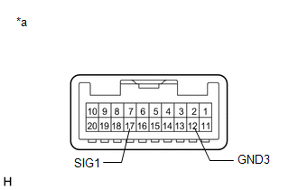
17 (SIG1) - 12 (GND3) |
Manual (SOS) switch not operated |
410 to 414 Ω |
|
17 (SIG1) - 12 (GND3) |
Manual (SOS) switch operated |
81 to 83 Ω |
| NG | | REPLACE ROOF CONSOLE BOX SUB-ASSEMBLY (MANUAL (SOS) SWITCH) |
|
| 6. |
CHECK HARNESS AND CONNECTOR (DCM (TELEMATICS TRANSCEIVER) - ROOF CONSOLE BOX SUB-ASSEMBLY (MANUAL (SOS) SWITCH)) |
(a) Disconnect the K140 DCM (telematics transceiver) connector.
(b) Disconnect the V18 roof console box sub-assembly (manual (SOS) switch) connector.
(c) Measure the resistance according to the value(s) in the table below.
Standard Resistance:
|
Tester Connection | Condition |
Specified Condition |
|---|---|---|
|
K140-21 (SIG1) - V18-17 (SIG1) |
Always | Below 1 Ω |
|
K140-3 (SIG-) - V18-12 (GND3) |
Always | Below 1 Ω |
|
K140-21 (SIG1) or V18-17 (SIG1) - Body ground |
Always | 10 kΩ or higher |
|
K140-3 (SIG-) or V18-12 (GND3) - Body ground |
Always | 10 kΩ or higher |
| NG | | REPAIR OR REPLACE HARNESS OR CONNECTOR |
|
| 7. |
REPLACE DCM (TELEMATICS TRANSCEIVER) |
(a) Replace the DCM (telematics transceiver) with a new one.
Click here
NOTICE:
- The engine switch must be off.
- Do not exchange the DCM (telematics transceiver) with one from another vehicle.
| NEXT | | PERFORM DCM ACTIVATION |
READ NEXT:
 Telephone Main Antenna Circuit Short to Ground (B15CB11,B15CB13)
DESCRIPTION This DTC is stored when the DCM (telematics transceiver) detects an open or a short in the telephone antenna (main) circuit.
DTC No. Detection Item
DTC Detection Condition T
Backup Battery Internal Electronic Failure (B15CC49)
DESCRIPTION This DTC is set when the DCM (telematics transceiver) detects one of the following:
The BUB (Back-Up Battery) voltage drops or the BUB (Back-Up Battery) malfunctions.
The BUB (Ba
Green Indicator Remains Off
DESCRIPTION After engine switch on (IG), the DCM (telematics transceiver) will enter into self check mode. The manual (SOS) switch red indicator will illuminate for 2 seconds and turn off followed by
SEE MORE:
Removal
REMOVAL PROCEDURE 1. REMOVE THROTTLE BODY WITH MOTOR ASSEMBLY
Click here 2. REMOVE NO. 2 SURGE TANK STAY
Click here
3. SEPARATE ENGINE WIRE
(a) Remove the 2 bolts and separate the engine wire.
(b) Remove the bolt and separate the earth wire.
4
Short to GND in Outer Mirror Indicator(Master) (C1AB2)
DESCRIPTION This DTC is stored when the blind spot monitor sensor RH detects a short to ground in the outer rear view mirror indicator RH.
DTC No. Detection Item
DTC Detection Condition Trouble Area
C1AB2 Short to GND in Outer Mirror Indicator(Master) Both of the following
