Toyota Camry (XV70): Telephone Main Antenna Circuit Short to Ground (B15CB11,B15CB13)
DESCRIPTION
This DTC is stored when the DCM (telematics transceiver) detects an open or a short in the telephone antenna (main) circuit.
|
DTC No. | Detection Item |
DTC Detection Condition | Trouble Area |
|---|---|---|---|
|
B15CB11 | Telephone Main Antenna Circuit Short to Ground |
Telephone antenna (main) impedance (Ω) is lower than the malfunction threshold for 10 seconds or more when the engine switch is on (IG) (Short circuit) |
|
| B15CB13 |
Telephone Main Antenna Circuit Open |
Telephone antenna (main) impedance (Ω) is higher than the malfunction threshold for 10 seconds or more when the engine switch is on (IG) (Open circuit) |
|
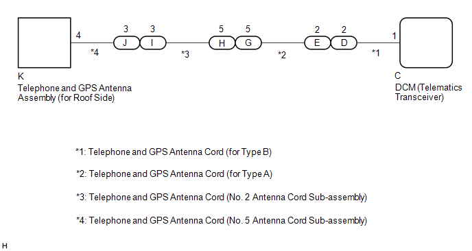
WIRING DIAGRAM
CAUTION / NOTICE / HINT
NOTICE:
Depending on the parts that are replaced during vehicle inspection or maintenance, performing initialization, registration or calibration may be needed. Refer to Precaution for Safety Connect System.
Click here .gif)
HINT:
Refer to "PARTS LOCATION" for the installation location of telephone and GPS antenna cord.
Click here
PROCEDURE
| 1. |
CHECK DTC |
(a) Turn the engine switch off.
(b) Connect the Techstream to the DLC3.
(c) Turn the engine switch is on (IG) and wait for 10 seconds or more.
(d) Turn the Techstream on.
(e) Clear the DTCs.
Body Electrical > Telematics > Clear DTCs(f) Recheck for DTCs.
Body Electrical > Telematics > Trouble CodesOK:
No DTCs are output.
| OK | .gif) |
CHECK FOR INTERMITTENT PROBLEMS |
|
.gif)
| 2. |
INSPECT TELEPHONE AND GPS ANTENNA ASSEMBLY (for Roof Side) |
| (a) Disconnect the telephone and GPS antenna assembly (for Roof Side) connector. |
|
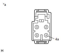
(b) Measure the resistance according to the value(s) in the table below.
Standard Resistance:
|
Tester Connection | Condition |
Specified Condition |
|---|---|---|
|
4 - 4a | Always |
9 to 11 kΩ |
| NG | | REPLACE TELEPHONE AND GPS ANTENNA ASSEMBLY (for Roof Side) |
|
| 3. |
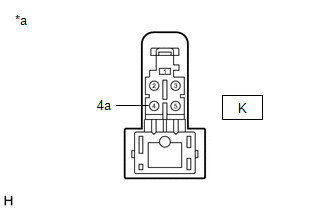
INSPECT TELEPHONE AND GPS ANTENNA CORD (NO. 5 ANTENNA CORD SUB-ASSEMBLY) |
| (a) Disconnect the K telephone and GPS antenna cord (No. 5 antenna cord sub-assembly) connector. |
|
| (b) Disconnect the J telephone and GPS antenna cord (No. 5 antenna cord sub-assembly) connector. |
|
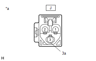
(c) Measure the resistance according to the value(s) in the table below.
Standard Resistance:
|
Tester Connection | Condition |
Specified Condition |
|---|---|---|
|
K-4 - J-3 | Always |
Below 1 Ω |
|
K-4 or J-3 - Body ground |
Always | 10 kΩ or higher |
|
K-4a - J-3a | Always |
Below 1 Ω |
|
K-4a or J-3a - Body ground |
Always | 10 kΩ or higher |
| NG | | REPLACE TELEPHONE AND GPS ANTENNA CORD (NO. 5 ANTENNA CORD SUB-ASSEMBLY) |
|
| 4. |
INSPECT TELEPHONE AND GPS ANTENNA CORD (NO. 2 ANTENNA CORD SUB-ASSEMBLY) |
| (a) Disconnect the I telephone and GPS antenna cord (No. 2 antenna cord sub-assembly) connector. |
|
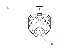
| (b) Disconnect the H telephone and GPS antenna cord (No. 2 antenna cord sub-assembly) connector. |
|
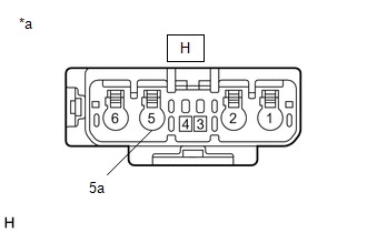
(c) Measure the resistance according to the value(s) in the table below.
Standard Resistance:
|
Tester Connection | Condition |
Specified Condition |
|---|---|---|
|
I-3 - H-5 | Always |
Below 1 Ω |
|
I-3 or H-5 - Body ground |
Always | 10 kΩ or higher |
|
I-3a - H-5a | Always |
Below 1 Ω |
|
I-3a or H-5a - Body ground |
Always | 10 kΩ or higher |
| NG | | REPLACE TELEPHONE AND GPS ANTENNA CORD (NO. 2 ANTENNA CORD SUB-ASSEMBLY) |
|
| 5. |
INSPECT TELEPHONE AND GPS ANTENNA CORD (for Type A) |
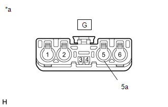
| (a) Disconnect the G telephone and GPS antenna cord (for Type A) connector. |
|
| (b) Disconnect the E telephone and GPS antenna cord (for Type A) connector. |
|
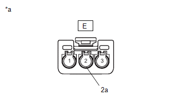
(c) Measure the resistance according to the value(s) in the table below.
Standard Resistance:
|
Tester Connection | Condition |
Specified Condition |
|---|---|---|
|
G-5 - E-2 | Always |
Below 1 Ω |
|
G-5 or E-2 - Body ground |
Always | 10 kΩ or higher |
|
G-5a - E-2a | Always |
Below 1 Ω |
|
G-5a or E-2a - Body ground |
Always | 10 kΩ or higher |
| NG | | REPLACE TELEPHONE AND GPS ANTENNA CORD (for Type A) |
|
| 6. |
INSPECT TELEPHONE AND GPS ANTENNA CORD (for Type B) |
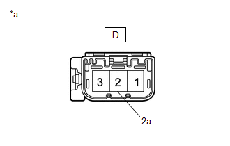
| (a) Disconnect the D telephone and GPS antenna cord (for Type B) connector. |
|
| (b) Disconnect the C telephone and GPS antenna cord (for Type B) connector. |
|
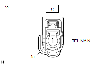
(c) Measure the resistance according to the value(s) in the table below.
Standard Resistance:
|
Tester Connection | Condition |
Specified Condition |
|---|---|---|
|
D-2 - C-1 | Always |
Below 1 Ω |
|
D-2 or C-1 - Body ground |
Always | 10 kΩ or higher |
|
D-2a - C-1a | Always |
Below 1 Ω |
|
D-2a or C-1a - Body ground |
Always | 10 kΩ or higher |
| NG | | REPLACE TELEPHONE AND GPS ANTENNA CORD (for Type B) |
|
| 7. |
REPLACE DCM (TELEMATICS TRANSCEIVER) |
(a) Replace the DCM (telematics transceiver).
Click here
NOTICE:
- The engine switch must be off.
- Do not swap the DCM (telematics transceiver) with one from another vehicle.
| NEXT | | PERFORM DCM ACTIVATION |
READ NEXT:
 Backup Battery Internal Electronic Failure (B15CC49)
DESCRIPTION This DTC is set when the DCM (telematics transceiver) detects one of the following:
The BUB (Back-Up Battery) voltage drops or the BUB (Back-Up Battery) malfunctions.
The BUB (Ba
Green Indicator Remains Off
DESCRIPTION After engine switch on (IG), the DCM (telematics transceiver) will enter into self check mode. The manual (SOS) switch red indicator will illuminate for 2 seconds and turn off followed by
Red Indicator Remains On
DESCRIPTION This means that the DCM (telematics transceiver) has detected a malfunction in the safety connect system and stored a DTC or specific vehicle control history (RoB) Code. PROCEDURE
1.
SEE MORE:
Cooling System
On-vehicle InspectionON-VEHICLE INSPECTION CAUTION / NOTICE / HINT
CAUTION: Do not remove the radiator cap sub-assembly while the engine and radiator assembly are still hot. Pressurized, hot engine coolant and steam may be released and cause serious burns.
PROCEDURE
1. INSPECT FOR COOLANT LEA
Components
COMPONENTS ILLUSTRATION
*1 NO. 1 ENGINE UNDER COVER
*2 NO. 2 ENGINE UNDER COVER ASSEMBLY
*3 FRONT WHEEL OPENING EXTENSION PAD LH
*4 FRONT WHEEL OPENING EXTENSION PAD RH
*5 FRONT FENDER APRON SEAL LH
- -
N*m (kgf*cm, ft.*lbf): Spe
