Toyota Camry (XV70): Linear Solenoid Power Supply System Malfunction (C120C)
DESCRIPTION
This DTC is output by the 4WD ECU assembly if a malfunction occurs in the linear solenoid power supply system.
|
DTC No. | Detection Item |
DTC Detection Condition | Trouble Area |
|---|---|---|---|
|
C120C | Linear Solenoid Power Supply System Malfunction |
|
|
|
Vehicle Condition | ||||
|---|---|---|---|---|
|
Pattern 1 | Pattern 2 |
Pattern 3 | ||
|
Diagnosis Condition | When the 4WD relay is on and the voltage at the IG1 terminal is 9.5 V or more |
○ | - |
- |
| When the 4WD relay is on and the voltage at the IG1 terminal is less than 9.5 V |
- | ○ |
- | |
| While the 4WD relay is off |
- | - |
○ | |
|
Malfunction Status | The 4WD relay monitor remains off |
○ | ○ |
- |
| The 4WD relay monitor remains on immediately after the ignition switch is turned to ON |
- | - |
○ | |
|
Detection Time | 1 second or more |
1 second or more | 1 second or more | |
|
Number of Trips | 1 trip |
1 trip | 1 trip | |
HINT:
DTC will be output when conditions for any of the patterns in the table above are met.
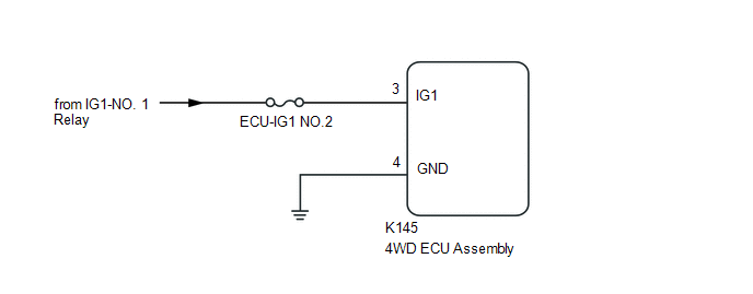
WIRING DIAGRAM
CAUTION / NOTICE / HINT
NOTICE:
Inspect the fuses for circuits related to this system before performing the following inspection procedure.
PROCEDURE
| 1. |
CHECK HARNESS AND CONNECTOR (IG1 TERMINAL) |
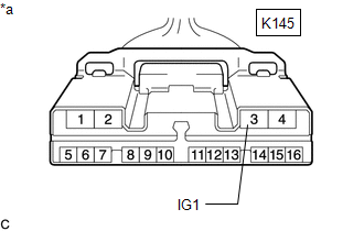
| (a) Disconnect the K145 4WD ECU assembly connector. |
|
(b) Turn the ignition switch to ON.
(c) Measure the voltage according to the value(s) in the table below.
Standard Voltage:
|
Tester Connection | Condition |
Specified Condition |
|---|---|---|
|
K145-3 (IG1) -Body ground |
Ignition switch ON | 11 to 14 V |
| NG | .gif) | REPAIR OR REPLACE HARNESS OR CONNECTOR |
|
.gif)
| 2. |
CHECK HARNESS AND CONNECTOR (GND TERMINAL) |
(a) Turn the ignition switch off.
(b) Measure the resistance according to the value(s) in the table below.
Standard Resistance:
|
Tester Connection | Condition |
Specified Condition |
|---|---|---|
|
K145-4 (GND) -Body ground |
Always | Below 1 Ω |
| NG | | REPAIR OR REPLACE HARNESS OR CONNECTOR |
|
| 3. |
RECONFIRM DTC |
(a) Clear the DTC.
Chassis > Four Wheel Drive > Clear DTCs(b) Turn the ignition switch to ON.
(c) Check that no DTCs other than DTC C120C have been output.
Chassis > Four Wheel Drive > Trouble Codes|
Result | Proceed to |
|---|---|
|
DTCs other than DTC C120C are not output |
A |
| DTCs other than DTC C120C are output |
B |
| A |
| REPLACE 4WD ECU ASSEMBLY
|
.gif)
| B |
| REPAIR CIRCUIT INDICATED BY OUTPUT CODE
|
READ NEXT:
 Low or High Power Supply Voltage (C1241)
DESCRIPTION If a malfunction in the power source circuit occurs, or a malfunction in communication with the skid control ECU (brake actuator assembly) or in a speed sensor occurs, the 4WD ECU assembly
Engine Circuit Malfunction (C1280)
DESCRIPTION If a malfunction in the ECM circuit occurs, the 4WD ECU assembly will output this DTC.
DTC No. Detection Item
DTC Detection Condition Trouble Area
C1280 Engine Cir
ABS Malfunction (C1296)
DESCRIPTION If a malfunction in the speed sensor signal circuit or yaw rate and acceleration sensor (airbag sensor assembly) circuit occurs, the 4WD ECU assembly will output this DTC.
The airbag sen
SEE MORE:
Disassembly
DISASSEMBLY CAUTION / NOTICE / HINT
NOTICE:
As imbalance affects vibration and noise performance, make sure to ensure correct angular alignment of the following components during installation.
PROPELLER INTERMEDIATE SHAFT ASSEMBLY
REAR PROPELLER SHAFT ASSEMBLY
LARGE DIAMETER PR
Freeze Frame Data
FREEZE FRAME DATA FREEZE FRAME DATA
HINT:
When a DTC is stored, the freeze frame data stores the current vehicle (sensor) state as.
The freeze frame data cannot be cleared or updated until the recorded DTCs are cleared.
Chassis > Brake
Tester Display Measurement Item
R
