Toyota Camry (XV70): Removal
REMOVAL
CAUTION / NOTICE / HINT
The necessary procedures (adjustment, calibration, initialization, or registration) that must be performed after parts are removed and installed, or replaced during antenna cord sub-assembly removal/installation are shown below.
Necessary Procedure After Parts Removed/Installed/Replaced|
Replaced Part or Performed Procedure |
Necessary Procedures | Effect/Inoperative Function when Necessary Procedure not Performed |
Link |
|---|---|---|---|
| Disconnect cable from negative battery terminal |
Perform steering sensor zero point calibration |
Lane Tracing Assist System |
|
|
Pre-collision System | |||
|
Memorize steering angle neutral point |
Parking Assist Monitor System |
| |
|
Panoramic View Monitor System |
|
CAUTION:
Some of these service operations affect the SRS airbag system. Read the precautionary notices concerning the SRS airbag system before servicing.
Click here .gif)
.png)
PROCEDURE
1. REMOVE INSTRUMENT PANEL SAFETY PAD SUB-ASSEMBLY
Click here
2. REMOVE NO. 2 SIDE DEFROSTER NOZZLE DUCT
Click here
3. REMOVE NO. 3 HEATER TO REGISTER DUCT SUB-ASSEMBLY
Click here
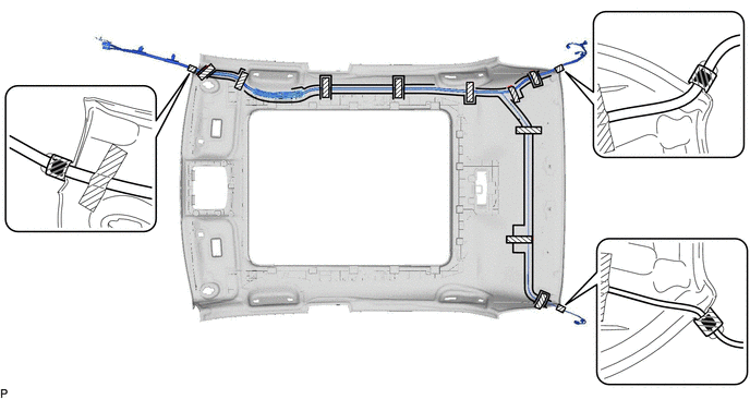
4. REMOVE ANTENNA CORD SUB-ASSEMBLY
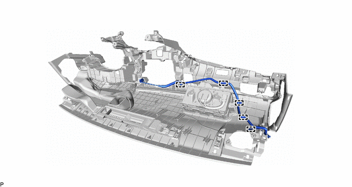
(a) w/o Navigation Antenna:
(1) Disengage the 5 clamps and remove the antenna cord sub-assembly.
(b) w/ Navigation Antenna:
(1) Disconnect the connector.
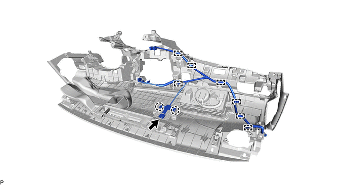
(2) Disengage the 2 claws.
(3) Disengage the 7 clamps and remove the antenna cord sub-assembly.
5. REMOVE ROOF HEADLINING ASSEMBLY
Click here
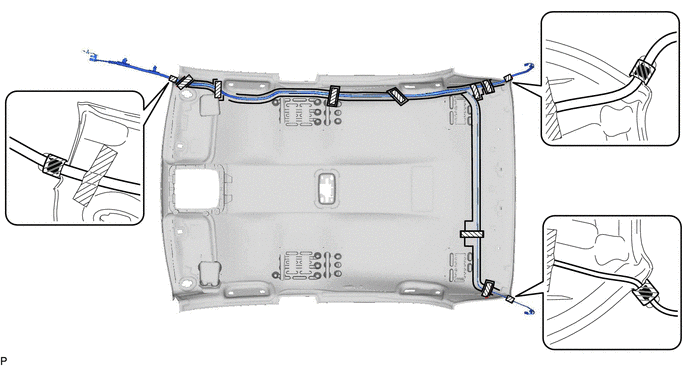
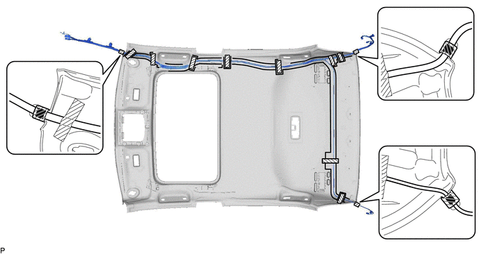
6. REMOVE NO. 2 ANTENNA CORD SUB-ASSEMBLY
(a) Remove the adhesive tape from the roof headlining assembly.
for Normal Roof:
 |
Adhesive Tape | - |
- |
for Moon Roof:
|
|
Adhesive Tape | - |
- |
for Panoramic Moon Roof:
|
|
Adhesive Tape | - |
- |
(b) Remove the No. 2 antenna cord sub-assembly from the roof headlining assembly.
7. REMOVE NO. 5 ANTENNA CORD SUB-ASSEMBLY (w/ Manual (SOS) Switch)
| (a) Disconnect the connector. |
|
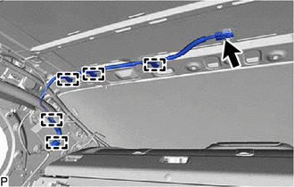
(b) Disengage the 5 clamps to remove the No. 5 antenna cord sub-assembly.
READ NEXT:
 Installation
INSTALLATION PROCEDURE 1. INSTALL NO. 5 ANTENNA CORD SUB-ASSEMBLY (w/ Manual (SOS) Switch)
(a) Engage the 5 clamps to install the No. 5 antenna cord sub-assembly.
(b) Connect the connector. 2. INS
Components
COMPONENTS ILLUSTRATION
*A for 7 Inch Display
*B for 9 Inch Display
*1 CENTER INSTRUMENT CLUSTER FINISH PANEL ASSEMBLY
*2 CENTER INSTRUMENT CLUSTER FINISH PANEL S
SEE MORE:
Disassembly
DISASSEMBLY PROCEDURE 1. REMOVE BRAKE MASTER CYLINDER STRAIGHT PIN
(a) Secure the brake master cylinder sub-assembly in a vise. NOTICE:
Place aluminum plates on the vise to prevent damage to the brake master cylinder sub-assembly.
(b) Using a 5 mm pin punch and a hammer, tap out the brake
Engine Circuit Malfunction (C1280)
DESCRIPTION If a malfunction in the ECM circuit occurs, the 4WD ECU assembly will output this DTC.
DTC No. Detection Item
DTC Detection Condition Trouble Area
C1280 Engine Circuit Malfunction
When the following continues for 5 seconds or more:
Communication wi
